
Waves InPhase is a phase-alignment and phase-manipulation plugin for related signals: two mono recordings, the two channels of a stereo recording, or a track compared with a sidechain reference. It combines sample/time alignment, 180° polarity inversion and frequency-dependent allpass phase shifting with captured waveform displays and a correlation meter. [1][2]
That makes it useful for problems such as a DI and microphone arriving at different times, drum close mics versus overheads, or left/right phase mismatch. It is not an automatic “make phase perfect” button. You choose the timing and phase changes while using the displays, correlation feedback and listening as evidence. [1][2]
My Short Version
Start with pure Delay before touching the phase-shift filters. Waves explicitly recommends timing alignment first. Capture a short section with a clear transient, zoom to a useful reference point, then move the Alpha/Beta waveforms into better time alignment. After that, use Phase Invert if a 180° reversal is appropriate, or enable Shelf/Bell allpass filters when the problem is frequency-dependent rather than a simple time offset. [1]
Use Mono Mix when phase cancellation in a summed signal is the concern, and watch the Correlation Meter as a diagnostic—not as a score that replaces listening. Positive correlation can be useful evidence, but different musical signals are not required to read +1. [1]
I did not align, null or measure tracks with InPhase for this article. The descriptions below come from Waves’ current documentation and visually inspected manual UI.
Components and latency
The current InPhase manual lists these components: [1]
- InPhase Mono
- InPhase Stereo
- InPhase LT Mono
- InPhase LT Stereo
- InPhase Live Mono
- InPhase Live Stereo
- InPhase Live LT Mono
- InPhase Live LT Stereo [1]
The manual states that all components have 20 ms latency, except Live components, which have no latency. The Delay control is separate: standard components can move it up to 20 ms in either direction, while Live components move it forward only. [1] The current InPhase product page's native-rate latency table lists Regular as 882, 960, 1,764 and 1,920 samples at 44.1, 48, 88.2 and 96 kHz, and Live as 0 at those rates. Its TD M48 row instead lists Regular 963 and Live 3 samples. The manual does not explain this platform-specific difference from its general statement. These are vendor-published specifications, not measurements or a per-host runtime guarantee; the named InPhase row should not be extended to the separately listed InPhase LT product. [2]
Waves also presents InPhase LT as a separate product. This guide covers full InPhase; the LT family relationship does not establish that the full InPhase product specifications apply to LT. [2]
Processing sections: Alpha, Beta and SC
InPhase has two processing sections. In Stereo components they are called Alpha and Beta. In Mono components they are Alpha and SC (sidechain). [1]
The names matter because the waveform/copy/paste controls refer to these sections directly.
Process routing
In Stereo components, Process chooses which signals fill Alpha and Beta: [1]
- selecting CH1 in Alpha forces CH2 into Beta, a configuration Waves recommends for a stereo track or a dual-mono pair such as bass amp and bass DI;
- selecting CH1/2 in Alpha forces the sidechain input into Beta, for aligning a stereo source to an external reference. [1]
In Mono components, the main audio is forced to Alpha and the sidechain to the comparison section. The manual includes a Logic-specific routing note about sending the reference to a bus before choosing that bus as the sidechain source. [1]
Activity LED
The Activity LED indicates input-signal activity in the processing section. The current manual does not publish a threshold, response time or default state, so none is invented here. [1]
Gain
Gain changes the level feeding a processing section. [1]
The current manual defines the function but does not publish a numeric range/default in its control text. The visible manual screenshot is therefore not used as proof of an undocumented range or default. Gain is also excluded from the captured-waveform processing display update, which is important when reading the graphs. [1]
Phase Invert
Phase Invert flips the signal by 180 degrees. [1]
This is the right tool for a pure polarity reversal, not for every timing/phase mismatch. If a cancellation problem changes with frequency, the Shelf/Bell allpass filters are the more targeted controls.
Phase Shift Curve Window
The Phase Shift Curve Window shows the phase-shift curve across frequency and updates as the filter parameters change. [1]
It is a visualization of the allpass processing, not an amplitude-EQ plot: the manual defines these filters as changing phase without changing the amplitude frequency response.
Phase filter Type
Each phase-shift filter can be set to: [1]
- Off
- Shelf — a first-order allpass filter;
- Bell — a second-order allpass filter. [1]
Shelf is defined by the frequency at which phase shift is 90°. Bell is defined by the frequency at which phase shift is 180° plus a Q factor controlling the rate/width of the phase transition. [1]
Frequency
Frequency selects the reference frequency for the allpass phase shift: 90° for Shelf or 180° for Bell. [1]
The current manual explains the function but does not publish the complete numeric range or default in its control text. Knob positions and screenshot labels do not establish those values. [1]
Q
Q controls the width/rate of the Bell filter’s phase transition. A narrower Q produces a faster phase transition toward the selected frequency and leaves a larger portion of the frequency range relatively intact. [1]
Again, the current manual documents the behavior but not a complete numeric range/default in the control text. No value is fabricated here.
Delay
Delay moves the signal by up to 20 milliseconds. Standard components can move in either direction; Live components move forward only. [1]
Waves recommends adjusting pure delay before adding phase-shift filtering. That is a useful workflow boundary because a timing problem and a frequency-dependent phase problem are not the same thing.
The standard non-Live component latency documented elsewhere in the manual is also 20 ms. Do not confuse plugin latency with the user’s Delay setting—they are separate facts in the guide. [1]
Monitor modes
The Monitor section lets you audition different signal combinations: [1]
- Stereo Mix — Alpha and Beta in stereo. When CH1/2 is compared with sidechain, the monitored output is attenuated 6 dB to compensate for summing.
- Mono Mix — Alpha and Beta/SC summed to mono, also attenuated 6 dB for the summed monitoring path.
- Alpha — Alpha only.
- Beta/SC — comparison section only. [1]
Mono Mix is especially useful when the practical problem is cancellation that appears when related sources are summed.
Output LED
The Output LED displays peak signal output level. [1]
The manual does not publish calibration details for this compact display. Treat it as a level/activity indicator, not a replacement for a dedicated peak meter.
Collapse
Collapse closes the waveform-display section. It changes the interface view rather than the underlying phase-processing parameters. [1]
Capture: Automatic and Manual
The waveform display works from a captured section of audio. The manual documents two capture modes: [1]
- Automatic — waits for a peak above -40 dBFS, then captures the following section and stops;
- Manual — capture begins when you click and ends when you click again, up to the documented limit. [1]
Maximum capture duration depends on sample rate:
- up to 2 seconds at 44.1/48 kHz;
- up to 1 second at 88.2/96 kHz. [1]
Choose a capture containing a clear shared event/transient when timing alignment is the goal.
Scroll Bar
The Scroll Bar moves along the captured waveform’s x-axis. It does not move the alignment marker itself. [1]
Correlation Meter
The Correlation Meter compares the captured Alpha and Beta waveforms after delay/phase processing. Its range is -1 to +1: [1]
- +1 — maximum correlation / identical signals;
- 0 — no correlation;
- -1 — completely out of phase according to the manual’s definition. [1]
A higher number is not automatically “better” for every pair of musical signals. Use correlation in the context of two recordings that are supposed to reinforce each other.
Correlation Markers and Value Box
The meter includes peak markers: blue for peak positive correlation and orange for negative peak correlation. The Correlation Value Box shows the current value in real time. [1]
Waves suggests trying a phase flip when negative correlation exceeds positive correlation. That is a documented troubleshooting suggestion, not a requirement to maximize the number at all costs.
Zoom X and Reset Zoom
Zoom X magnifies the captured waveform’s time axis down to sample resolution. Reset Zoom restores the default x-axis view. [1]
Use horizontal zoom when a transient or zero crossing needs closer inspection.
Zoom Y Alpha, Zoom Y Beta and Zoom Y Link
Zoom Y Alpha and Zoom Y Beta adjust the amplitude-axis view independently. Zoom Y Link ties the two vertical zoom controls together. [1]
These are display controls. They do not change the processed audio.
Waveform displays
The Alpha/Beta waveform displays show the captured signals and update in real time according to the delay and phase processing. The manual explicitly says gain changes are excluded from that waveform update. [1]
That distinction prevents a level adjustment from being mistaken for an alignment change in the visual display.
Marker
The Marker sets the center position for zoom and provides a reference for aligning peaks/zero crossings. Scrolling does not move it and can move it outside the visible area. The manual also notes an Alt/Option-assisted marker gesture over the waveform. [1]
Copy Alpha/Beta and Paste
Copy Alpha Beta copies section settings to the InPhase clipboard so they can be moved between components/instances. [1]
- Paste Alpha pastes the saved Alpha settings into Alpha.
- Paste Beta pastes saved Beta settings into Beta; in the Mono component, the manual says Beta settings are pasted to Alpha. [1]
This is InPhase-specific settings transfer, separate from the host’s normal preset management.
WaveSystem toolbar
The top WaveSystem bar provides preset load/save, compare, undo/redo and resize behavior. [1] These are shared plugin-management controls, not part of the phase-processing algorithm.
A practical InPhase workflow
For two related recordings, route them so one appears in Alpha and the other in Beta/SC. Capture a short section containing a clear shared transient, choose Mono Mix when summed behavior matters, and put the marker on a useful reference point. [1]
Adjust Delay first to align the timing/zero crossing. Check correlation and compare processed with unprocessed audio using the manual's documented A/B option. If a frequency region still cancels, enable one Shelf or Bell allpass filter and sweep Frequency; use Q for Bell width. Add a second filter only if a separate frequency region needs independent phase rotation. [1]
Use Phase Invert when the whole relationship is closer to a 180° polarity reversal. Do not pile all three correction methods on automatically.
This is documentation-led editorial guidance based on Waves’ examples. No phase-alignment test was performed for this article.
Best for / skip if
InPhase is best for related sources that should combine coherently but arrive with timing and/or phase differences: multi-miked instruments, DI-plus-mic recordings, stereo-channel problems or a track compared with an external sidechain reference. [1][2]
Skip it when the recordings are intentionally unrelated, when a simple sample/time nudge in the DAW solves the issue more transparently, or when the production should preserve the existing phase relationship. Correlation is not a reason to homogenize intentionally different signals.
Limitations and evidence boundary
This article is documentation-led. I did not perform a null test, measure plugin latency, align drum/bass recordings, verify the -40 dBFS trigger threshold independently, or compare standard versus Live sound/latency in a host.
The current manual fully explains the user-facing functions audited here, but it does not publish numeric ranges/defaults for Gain, allpass Frequency or Q in the control text. Those omissions are stated explicitly rather than inferred from screenshots. [1]
Interface reference
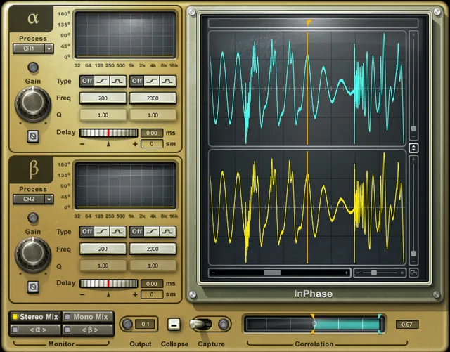
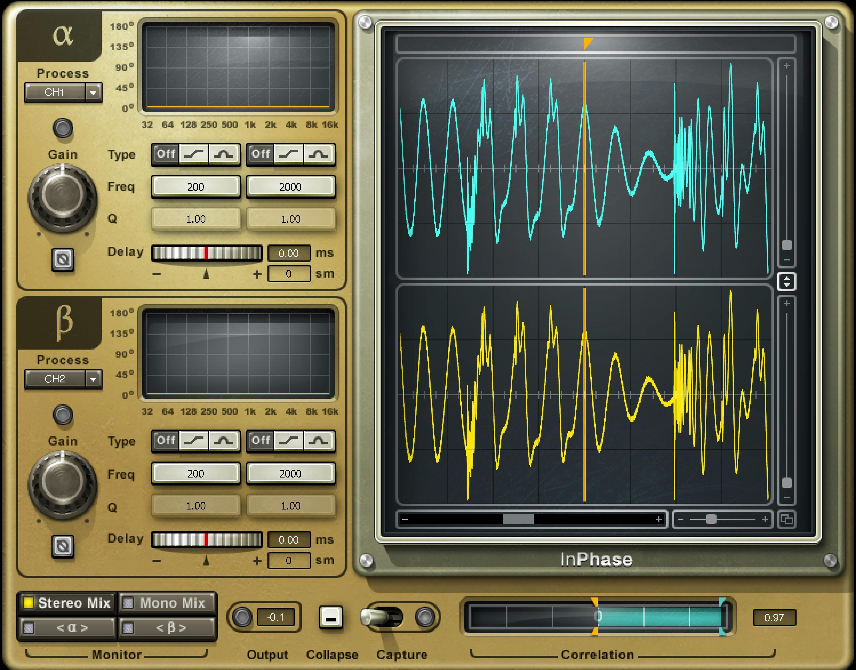
Waves' InPhase interface artwork shows Alpha/Beta controls alongside waveform displays and a correlation meter. The pictured waveforms, correlation value and parameter settings are illustrations, not measured results, defaults or proof of an installed build. [3]
Related guides
For official InPhase documentation and support, visit Waves Support.
Bottom line
InPhase separates three different correction jobs that are often lumped together: timing offset, 180° polarity reversal and frequency-dependent phase rotation. Delay addresses timing, Phase Invert addresses polarity, and Shelf/Bell allpass filters rotate phase around selected frequencies. Capture, waveform zoom and correlation feedback make those decisions visible without pretending the meter can decide what sounds right. [1]
Sources
Checked October 18, 2026. No listening, phase-alignment, latency or native-host test was performed.
- Waves InPhase User Guide, current product-linked guide; full control text parsed and interface/capture/correlation pages visually inspected.
- Waves InPhase product page, current product identity, positioning, thumbnail, manual link and vendor latency table.
- Waves Graphic Library, current InPhase listing and product-image reuse rule requiring a relevant Waves product backlink.
FAQ
What does Waves InPhase do?
Waves describes InPhase as a tool for phase alignment and manipulation between related signals. Its documented tools include delay, 180° Phase Invert, frequency-dependent allpass filters, captured waveform displays and a correlation meter. [1][2]
Should I adjust delay or phase shift first?
The guide recommends adjusting pure delay before adding phase shift. Its examples then suggest a Shelf or Bell allpass filter if a frequency region still loses energy after delay adjustment. [1]
What is the difference between Phase Invert and the phase filters?
Phase Invert flips the signal by 180°. Shelf and Bell are first- and second-order allpass filters that change phase without changing the amplitude frequency response; the Bell filter also uses Q to control the phase-transition width. [1]
What does the InPhase correlation meter mean?
The guide describes a scale from −1 to +1 for the captured Alpha/Beta signals after delay and phase processing: 0 means no correlation, +1 maximum correlation/identical signals, and −1 completely out of phase. Treat it as diagnostic information about related signals, not a universal target. [1]
How much delay and plug-in latency does Waves document?
The manual says standard components can move Delay up to 20 ms in either direction and Live components forward only. Separately, it states 20 ms plug-in latency for all components except Live, which it calls zero latency. The current InPhase product table lists Regular/Live latency in samples at 44.1/48/88.2/96 kHz as 882/0, 960/0, 1,764/0 and 1,920/0; its TD M48 row lists 963/3 samples. That platform-specific row differs from the manual's general statement and is not reconciled there. These are vendor specifications, not independent measurements or host-runtime guarantees; do not apply the full InPhase table to InPhase LT. [1][2]
How long can InPhase capture for waveform alignment?
The guide documents up to two seconds at 44.1/48 kHz and up to one second at 88.2/96 kHz. Automatic mode waits for a peak above −40 dBFS and captures the following interval; Manual mode starts and stops capture when clicked. [1]
How do the LT and Live components differ?
The guide calls LT a simplified version for creative phase manipulation; the Waves site also lists InPhase LT separately from InPhase. Live is a separate component family: the guide says Live delay is forward-only and its latency is zero, unlike the general 20 ms statement for non-Live components. Do not treat the full InPhase product-page sample table as a separately verified LT specification. [1][2]
Does the guide publish numeric ranges or defaults for Gain, Frequency and Q?
The current guide defines Gain as the level entering a processing section, Frequency as the Shelf/Bell phase-shift reference, and Q as the Bell transition-width control. Its control text does not give complete numeric ranges or defaults for these controls, so screenshot values should not be presented as universal settings. [1]

About the Author
Joseph Nilo has been working professionally in all aspects of audio and video production for over twenty years. His day-to-day work finds him working as a video editor, 2D and 3D motion graphics designer, voiceover artist and audio engineer, and colorist for corporate projects and feature films.