
Waves Kramer Master Tape models a tube tape-recording path, with controls for drive, tape speed, bias, flux, modulation and noise. It also includes a separate slap/feedback-delay section. Record Level changes the drive into the model, while Playback Level helps establish the resulting output level. [1][2]
Two distinctions prevent common mistakes: Input monitoring is not full-plugin bypass, and VU calibration changes the meter reference rather than the sound.
This is a guide to the documented controls and suggested evaluation choices. It does not report a new tape-model comparison.
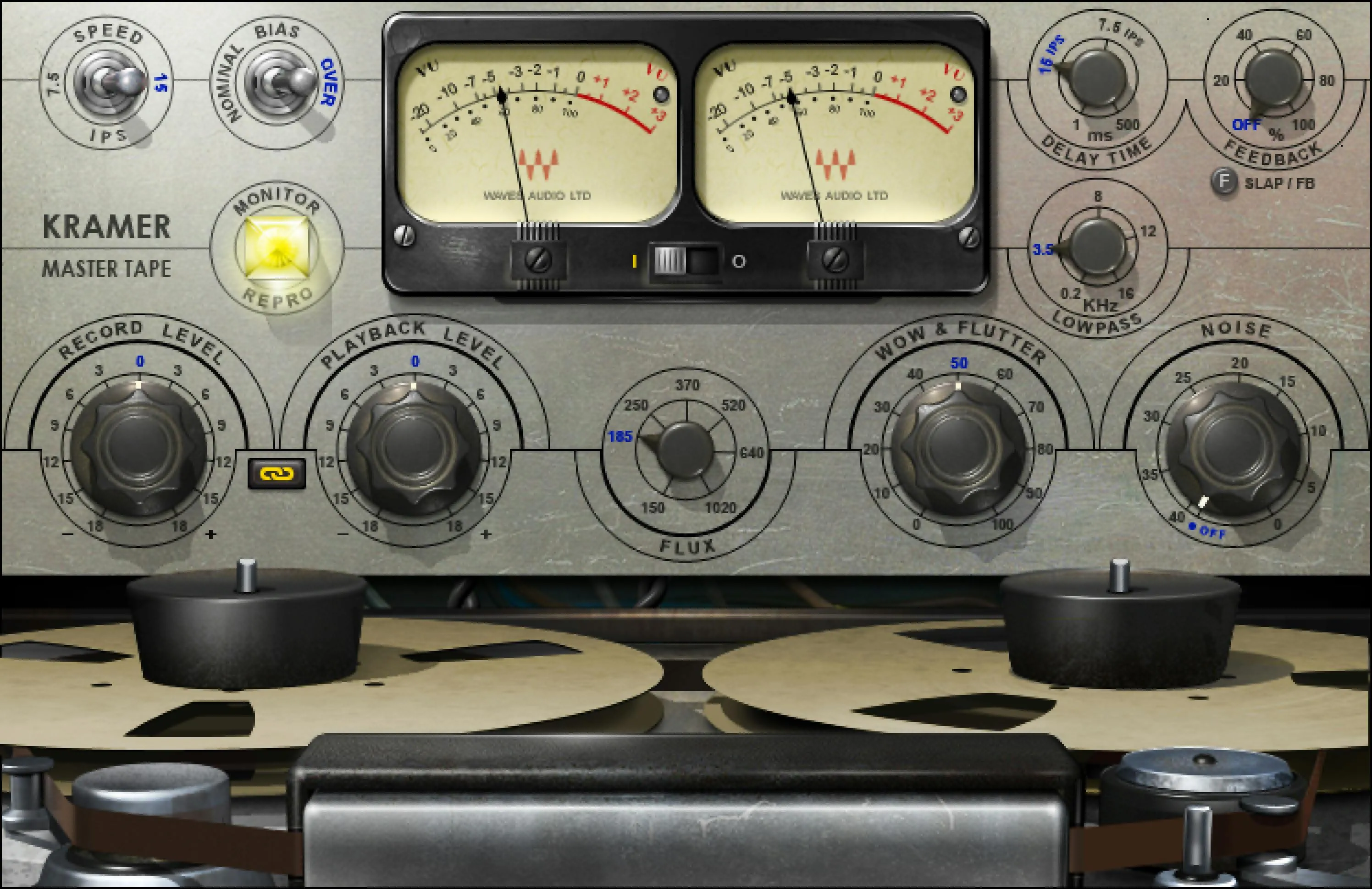
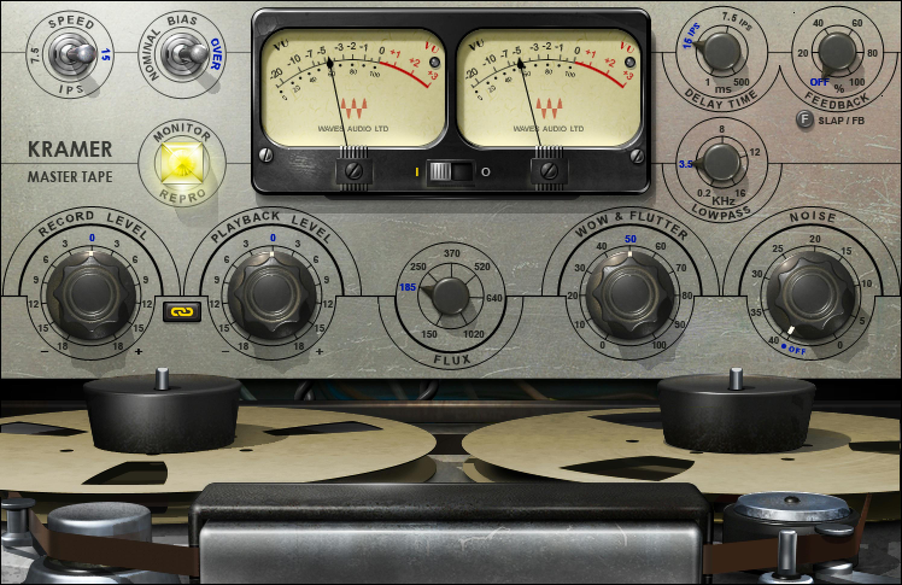
About the imagery: the cover is an editorial illustration. The plugin interface is official Waves product artwork, not a capture of a listening or compliance test.
My Short Version
Decide whether you want subtle coloration, stronger saturation or a delay effect. Do not adjust all three goals at once.
Start with delay and added noise out of the decision. Use Record Level, Flux and Playback Level deliberately, comparing at similar loudness.
Add instability or echo only when it serves the track. A model of imperfect hardware does not require every imperfection to be turned up.
What the model includes
Waves describes a quarter-inch tube-machine model developed with Eddie Kramer. The processing includes electronic and tape behavior, not only an EQ curve. Mono and Stereo components share the main control design. [1, pp.3–7][2]
For a music track, the task may be a change in density or character. For dialogue, coloration is an intentional creative decision rather than a general cleanup step.
Keep the original sound available. A stronger effect can be useful and still be wrong for the current programme.
Drive and output controls
Record Level
Record Level changes the level entering the model. Its documented range is -18 to +18 dB, default 0. [1, p.12]
Use it to decide how hard the source drives the processing. A louder input can change character as well as level, so lowering the output afterward does not undo every effect of increased drive.
Choose a representative strong passage and return to quieter material before deciding. An effect that works on the chorus may be too obvious on an exposed line.
Playback Level
Playback Level controls the overall output, also -18 to +18 dB, default 0. [1, p.12]
Use it to maintain a useful comparison. Do not leave a large loudness advantage in place and attribute the entire improvement to tape character.
Link I/O
Link I/O couples Record and Playback Level inversely: increasing one is accompanied by a compensating movement in the other. The manual lists Linked as the default. [1, p.12]
That helps compare different drive amounts, but a linked adjustment is not proof of exact perceptual loudness matching. Recheck the result by ear and meter as appropriate.
Tape-character controls
Speed
Speed chooses 7.5 or 15 inches per second, with 15 ips as the documented default. The modeled frequency and noise behavior changes with that selection. [1, pp.4,10]
Choose it as part of the sound, not as a quality setting where the larger number must win.
The separate delay time is not automatically determined by this transport-speed switch. The manual's delay discussion explicitly separates them.
Bias
Bias offers Nominal or Over, default Over. It changes the modeled tape-bias condition; it is not another output-volume knob. [1, pp.4,10]
Compare it with the same source and a comparable level. Descriptive hardware terminology is not a substitute for deciding whether the result fits the mix.
Flux
Flux changes the modeled tape operating level. The documented range is 150–1,020 nWb/m, default 185 nWb/m. [1, p.12]
This is another influence on the tape behavior, separate from Record Level. Do not treat an extreme value as a more authentic version of the default.
Change one drive-related control at a time when learning the plugin. Otherwise, it becomes difficult to identify which choice caused a useful—or unwanted—difference.
Wow & Flutter
This sets modeled speed and gain fluctuations. The documented scale is 0–100, default 50, described as the modeled reference amount. [1, p.13]
Sustained notes can reveal a different consequence from a short percussive hit. For spoken-word material, listen to the stability and character of the voice rather than assuming movement adds value.
The control's number is not a published percentage of pitch deviation. Do not invent that conversion.
Noise
Noise controls the added modeled noise. The manual provides Off or -40 to 0 dB relative to its modeled reference, with Off as the default. [1, p.13]
Leaving Noise off does not bypass the entire tape model. Decide whether added noise is part of the intended effect, especially in pauses or at the end of a programme.
A number near zero here is not a claim that the final recording's noise floor measures 0 dBFS.
Monitor versus meter selection
Monitor: Input or Repro
Input monitors the modeled input tube stage. Repro includes the tape and output portions of the documented path; Repro is the default. [1, p.10]
Input is not clean host bypass. Use it to investigate the stages of the model, and use full-plugin bypass when the comparison needs the unprocessed source.
VU Input/Output selector
The I/O switch on the meter selects the level being displayed. The manual explicitly says it does not change the monitored sound. [1, p.20]
Do not confuse a meter transfer with the separate Input/Repro monitoring choice. One changes what you look at; the other changes the modeled path you hear.
VU calibration screw
The small, unlabelled screw beneath the meter adjusts its reference. Its documented range is -24 to -8 dBFS, default -18 dBFS; the left screw calibrates both meters in the Stereo component. [1, p.11]
Changing calibration does not reduce drive or repair a peak. It changes where the meter places its reference.
The VU display spans the modeled -20 to +3 VU range. It is not an integrated-loudness or true-peak meter, and 0 VU is not synonymous with digital full scale. [1, p.10]
The manual does not establish a separate held-peak reset gesture for this modeled needle. Do not invent one from another product's meter.
The delay controls
Delay Time
Delay Time sets the echo timing. The controls chapter gives 1–500 ms, default 133 ms, with marked 133/266 ms positions corresponding to the illustrated tape-delay references. [1, p.11]
The appendix gives a 0 ms lower endpoint instead. That discrepancy remains a documentation limit; this guide uses the explicit controls chapter and does not claim a measured minimum.
Choose this control for the echo timing. Changing the main Speed setting does not automatically select the delay time.
Delay Type: Slap or Feedback
The type switch chooses Slap or Feedback, default Feedback. [1, p.11]
These support different effect decisions. Judge the first repeat and the continuation separately, and keep the delay level restrained while changing modes.
Delay Level / Feedback amount
The delay amount control runs from Off to 100, default Off. Its displayed role follows the selected Slap/Feedback behavior. [1, p.11]
The appendix describes the feedback path returning delayed output toward the input, with the direct signal retained. This is not a full-featured independent delay with every possible wet/dry and routing option.
Increase it cautiously and listen beyond the initial phrase. A useful short echo can become a distracting continuation when the arrangement leaves space.
Lowpass
Lowpass filters the delay path, over 200 Hz–16 kHz, default 3.5 kHz. [1, p.12]
This lets the repeat occupy a different tonal space. It is not a general high-cut control for the entire direct signal.
Check the repeat in context rather than making it dark simply because tape-delay presets often sound that way.
Components, presets and common toolbar
Mono and Stereo components are documented. The stereo meter calibration uses the left screw for both channels; no separate undocumented mid/side or independently modeled channel mode is assumed here. [1, pp.7,11]
The WaveSystem toolbar provides About, Undo/Redo, preset load/save, Previous/Next, Setup A/B, Copy A/B, sizing and help. The current preset browser also provides search, Factory/User/Favorite views, favorites, Copy/Paste, Reset to Default and Detach. [3][4]
A/B compares two settings inside the model. Check Monitor, Delay Level and Noise in both setups before attributing every difference to one knob.
A focused first evaluation
Choose the goal first. For coloration, keep delay and added noise out of the initial comparison.
Set a sensible Record Level, try a limited change in Flux or Speed, and compare through Playback Level or linked I/O at a similar listening level. Then check the quiet and exposed sections.
For a delay effect, set the timing and type at low amount before refining the delay-path Lowpass. Listen to the tail after the phrase, not just the sound while the source is present.
Keep monitoring level comfortable. This suggested method does not require extreme gain, and no new test result is claimed here.
Related plugins
J37 Tape is another Waves tape model with different controls and modeled choices. The name alone does not establish which is better for a track.
Kramer HLS Channel is a related console-channel model, a different stage of the recording-chain concept rather than a substitute for every tape effect.
RComp is the clearer reference when the job needs explicit compressor timing and ratio rather than tape behavior. L2 addresses a separate final-peak-control task.
The Waves resource hub connects the broader toolkit and licensing guides.
Bottom line
Separate drive, tape behavior, monitoring and delay in your decisions. Record Level and Flux shape the processing, Playback Level helps compare it, and meter calibration only changes the reference you see.
Use the model for a defined effect. Do not treat more noise, movement or drive as automatic evidence of a better recording.
Sources
Checked September 19, 2026. No newly measured sonic, hardware-equivalence or compatibility result.
- Kramer Master Tape User Guide, pp.4–13 and delay/meter clarification pp.20–21.
- Waves Kramer Master Tape.
- WaveSystem guide.
- Waves preset instructions.
- Waves Graphic Library.
Frequently Asked Questions
Is Kramer Master Tape's Input monitor mode the same as bypass?
No. Input mode still monitors the modeled input tube stage; Repro adds the tape and output stages. Use the host or plugin's full bypass when you need to compare against the unprocessed source.
Do the VU I/O switch and calibration screw change the sound?
The I/O switch only chooses whether the meter displays plugin input or output, and the manual says it has no effect on monitored sound. The calibration screw changes the VU reference, from -24 to -8 dBFS with -18 dBFS as the default; it is not a gain or limiter control.
How do Record Level, Playback Level, and Link I/O differ?
Record Level changes the input feeding the model, so it can alter drive and character. Playback Level controls total output. Link I/O moves the two controls inversely, which helps comparisons but does not prove exact perceptual loudness matching.
Does the 7.5 or 15 ips Speed switch set Kramer Master Tape's delay time?
No. Speed changes the modeled tape-speed behavior, including frequency and noise characteristics. Delay Time is a separate control, and the manual explicitly says the delay is not affected by transport Speed; the 133 ms and 266 ms marks are reference positions.
Is Kramer Master Tape's minimum delay time 0 ms or 1 ms?
The official manual is inconsistent: the controls chapter states a continuous 1-500 ms range, while the appendix states 0-500 ms. Use 1-500 ms when quoting the explicit control specification, and do not claim that 0 ms was independently measured.
What is the difference between Record Level and Flux in Kramer Master Tape?
Record Level controls the input level entering the model. Flux changes the modeled tape operating level, documented from 150 to 1,020 nWb/m with 185 nWb/m as the default. They are separate influences on the result, so change one at a time when learning the plugin.

About the Author
Joseph Nilo has been working professionally in all aspects of audio and video production for over twenty years. His day-to-day work finds him working as a video editor, 2D and 3D motion graphics designer, voiceover artist and audio engineer, and colorist for corporate projects and feature films.