
MV360 is Waves' dual-path dynamics processor for 5.0 and 5.1 surround. Low Level Compression raises material below its threshold; High Level Compression controls material above its threshold, with automatic makeup gain and a separate volume trim.
Its defining practical choice is which channels respond together. Link mode determines both parameter links and detector/compression groups, rather than merely moving faders together.
I read the complete 14-page guide and current official sources and inspected the genuine interface. I have not auditioned MV360 or measured its dynamics, noise or channel response.
My Short Version
Low Threshold addresses quieter material. Low Volume then adjusts makeup for that compressed low-level signal.
High Threshold addresses louder material. High Volume trims the high path's automatic compensation.
Single-bank masters and paired masters are different. One moves only Threshold or Volume; the paired control moves both relatively.
Choose the component before counting modes. Five choices belong to 5.1, four to 5.0—not nine in either menu.
Best for and when to use something else
Best for: a surround stem or programme that needs separate low-level and high-level dynamics treatment while preserving a chosen relationship among front, rear, center and LFE channels.
It is not a gate, an independent per-frequency dynamics editor or a loudness meter. The F6 guide describes frequency-specific dynamics; WLM Plus addresses separate loudness measurement.
If the task is simply matching a delivery loudness specification, a multichannel compressor setting is not proof of that result. Channel balance and level still need independent evaluation.
Two paths, two components and automatic dither
The guide lists MV360 5.0 to 5.0 and MV360 5.1 to 5.1. Six discrete channels describes the latter; a 5.0 component does not gain an LFE channel.
Low Level Compression reduces dynamic range by pushing signals below its threshold upward. High Level Compression combines compression, automatic makeup gain and output-level control. This is not a documented serial routing diagram or an invitation to invent attack, ratio, knee or release controls.
The guide says dither is automatically applied. It supplies no Dither switch, selectable bit depth or noise-shaping menu. Another Waves processor's IDR controls do not establish hidden MV360 options.
Low Threshold and Low Volume
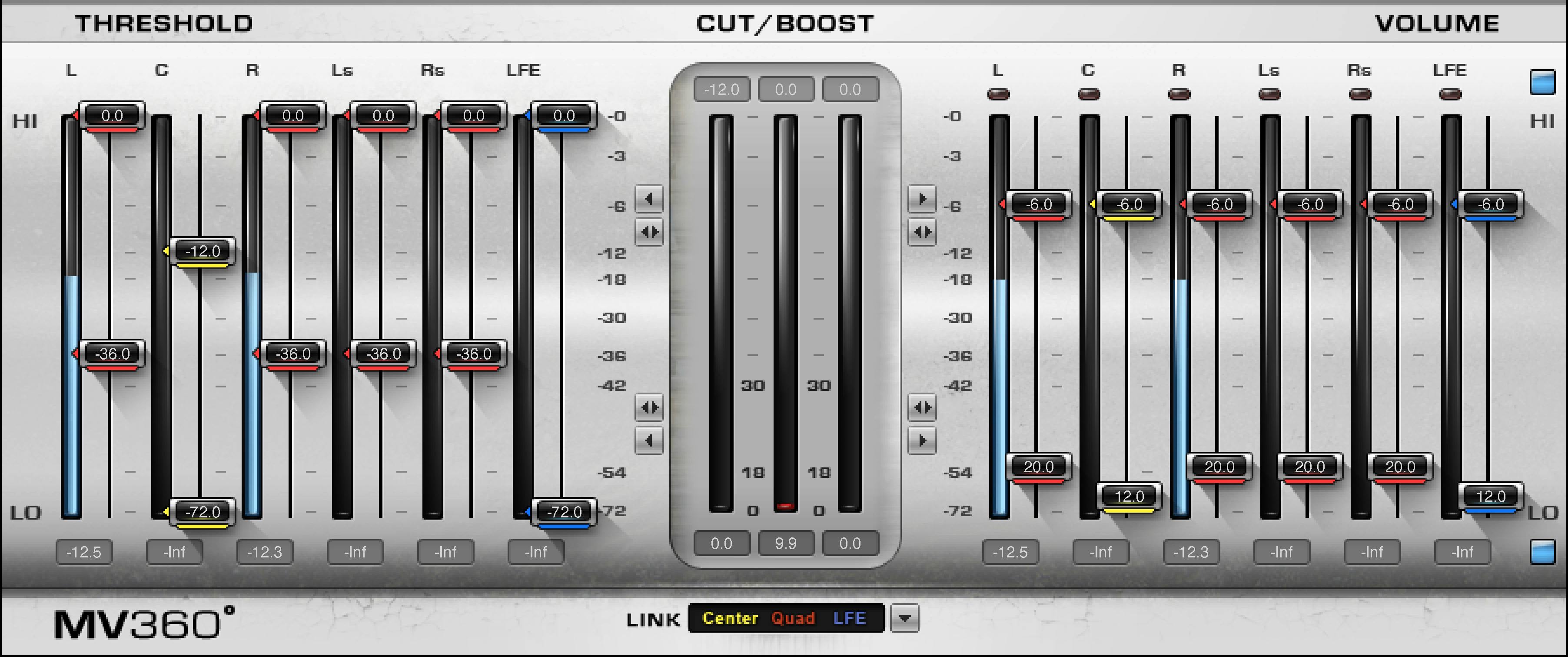
Low Threshold spans −36 to −72 dBFS. Compression applies below the chosen threshold.
Moving that reference is different from changing the makeup amount. Low Volume spans 0 to +30 dB and adjusts makeup applied to the compressed low-level signal.
The guide documents a separate Low Level Compression On/Off control. It does not state a factory default for that switch or for these faders.
Raising quiet detail can also raise unwanted material within that low-level content. That is a conceptual reason to evaluate the source and not treat upward compression as noise removal.
High Threshold, High Volume and the unit qualification
High Threshold spans 0 to −30 dBFS. Material above it is compressed. Automatic makeup compensates for the resulting reduction.
High Volume trims that compensation. Page 9 literally prints its range as 0 to −30 dBFS, even though the function is described as a gain trim. That is the guide's unit wording, not an independently verified relative-gain specification.
A separate High Level Compression On/Off switch is documented. Its default, and a universal starting value for the high faders, are not stated.
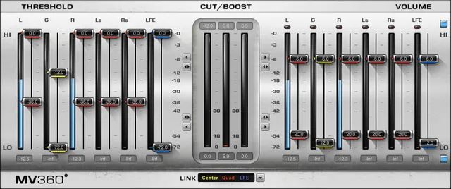
The pictured settings are examples. They do not establish that the switch starts enabled or that a shown −6.0 value is the factory trim.
All six relative master functions
The interface's arrow controls have six documented functions:
- High Level Compression Masters: move all High Threshold and High Volume faders by equal relative amounts.
- High Level Threshold Master: moves only all High Threshold faders relatively.
- High Level Volume Master: moves only all High Volume faders relatively.
- Low Level Compression Masters: move all Low Threshold and Low Volume faders relatively.
- Low Level Threshold Master: moves only all Low Threshold faders relatively.
- Low Level Volume Master: moves only all Low Volume faders relatively.
“Relative” means each starts from its existing value; it does not mean all channels acquire the same displayed number.
The paired/double-arrow function therefore differs from a single-bank arrow. No independent master range, default or detailed endpoint-clamping algorithm is published.
Link modes: detector grouping and parameter grouping
Link selection changes the interface control links and the detector/compression groups. Colors identify the resulting groups in the threshold, volume and Cut/Boost sections.
The five 5.1 choices are:
| Link mode | Documented grouping |
|---|---|
| All Linked | All six channels respond together. |
| 5 Linked | LFE | Main five together; LFE separate. |
| Front | Rear | LFE | L/C/R; Ls/Rs; LFE. |
| Center | Quad | LFE | C; L/R/Ls/Rs; LFE. |
| Center | Front LR | Rear | C; L/R; Ls/Rs, with LFE bypassed. |
That last mode leaves LFE unprocessed, rather than creating a fourth dynamics group.
The four 5.0 choices are All Linked, Front | Rear, Center | Quad, and Center | Front LR | Rear.
Their described channel sets are respectively all five; L/C/R plus Ls/Rs; C plus L/R/Ls/Rs; and C plus L/R plus Ls/Rs. No LFE processing is added to 5.0.
Appendix wording and what it does not establish
Pages 13–14 call the 5.0 Front | Rear and Center | Quad modes “3 separate sidechains,” but enumerate only two groups for each. The wording is inconsistent; there is no documented third channel group to add.
The 5.0 All Linked paragraph also mentions maintaining balance with LFE, despite the explicit five-channel component. The component inventory and listed main-channel groups remain the usable scope; the stray LFE wording is not a new 5.0 feature.
These qualifications are distinct from the fully enumerated three-group 5.0 Center/Front/Rear mode. They do not turn the nine aggregate choices into nine choices per component.
Cut/Boost meters and separate input/output displays
The three colored Cut/Boost meters correspond to up to three active link groups. Attenuation grows downward; boost grows upward.
Their extent is −30 dB attenuation to +30 dB boost. Top numeric fields show maximum attenuation and bottom fields maximum gain. Click anywhere on the relevant meter to reset those maximum values.
The actual interface separately has input/output bars, numeric fields and small top indicators. Their complete calibration, ballistics, reset gestures and indicator algorithm are not supplied in the guide.
The Cut/Boost reset instruction is therefore not extended to every numeric field. None of these displays is a documented integrated-loudness or true-peak mode.
Toolbar and a practical setup order
The common WaveSystem toolbar provides save/load presets, compare, undo/redo, resizing and access to its guide. The Library panel does not show the toolbar; this does not establish removal.
My suggested sequence: choose the correct channel component, decide which channels should share detection, then consider low and high thresholds separately. Use the corresponding Volume bank for compensation and the correct relative master when changing several settings.
Watch each group's Cut/Boost display alongside independent input/output levels. Evaluate whether lifting quiet material is useful before combining it with stronger high-level compression.
The guide's Front/Rear/LFE quick-start choice is advice, not a declared factory default or a tested preset from this article.
Sources and documentation limits
Checked October 19, 2026, America/New_York. The official MV360 page links the complete 14-page guide, read in full.
Pages 3–5 explain the two paths, link concepts and automatic dither; 6 components/toolbar; 7 workflow; 8 interface; 9 ranges/switches; 10 masters; 11 links/meters; 12–14 channel groupings and appendix inconsistencies.
The genuine Graphic Library original was inspected. High Volume's dBFS label, the 5.0 appendix wording and unspecified defaults/meter details remain explicit. Vendor benefits are not listening or measurement results.
The Waves resources hub and licensing guide cover separate reference topics.
FAQ
What does MV360 do to quiet and loud signals?
Low Level Compression raises signals below its threshold. High Level Compression attenuates signals above its threshold and has automatic makeup gain plus a volume trim. The guide does not expose attack, ratio, knee or release controls, and no dynamics response was measured here.
What are the Low Threshold and Low Volume ranges?
Low Threshold spans minus 36 to minus 72 dBFS; Low Volume spans 0 to plus 30 dB and controls makeup for the compressed low-level signal. A separate Low Level Compression On/Off switch is documented. Factory defaults are not stated for these controls.
How should I read High Volume's dBFS range?
Page 9 describes High Volume as trimming automatic gain compensation but prints 0 to minus 30 dBFS. That literal unit is retained rather than converted into a verified gain specification. High Threshold separately spans 0 to minus 30 dBFS; their defaults are not stated.
How do the six master functions differ?
Each high or low compression paired master moves both Threshold and Volume relatively. Separate Threshold and Volume masters move only their corresponding banks. Existing offsets are preserved by the described relative movement; no independent master range, default or endpoint algorithm is specified.
Are all nine link modes available in each component?
No. Five belong to 5.1 and four to 5.0. The modes link both parameters and detector/compression groups. The 5.1 Center/Front LR/Rear mode leaves LFE unprocessed. A 5.0 component has no added LFE channel.
Why does the 5.0 appendix mention three sidechains and LFE?
Its Front/Rear and Center/Quad paragraphs say three sidechains but enumerate two groups, and its All Linked paragraph mentions LFE despite the five-channel component. Those wording inconsistencies remain qualified; they do not establish a third group or LFE processing in 5.0.
Which meter reset is documented?
Clicking a colored Cut/Boost meter resets its maximum attenuation and boost fields. Its displayed extent is minus 30 to plus 30 dB. The separate input/output meters have no fully specified calibration, ballistics, reset gestures or indicator algorithm in the guide.
Does MV360 have selectable dither settings or a preset toolbar?
The guide says dither is applied automatically but supplies no switch, bit-depth selector or shaping menu. WaveSystem separately provides save/load presets, comparison, undo/redo, resizing and help. The Library panel's missing toolbar does not prove those functions were removed.

About the Author
Joseph Nilo has been working professionally in all aspects of audio and video production for over twenty years. His day-to-day work finds him working as a video editor, 2D and 3D motion graphics designer, voiceover artist and audio engineer, and colorist for corporate projects and feature films.