
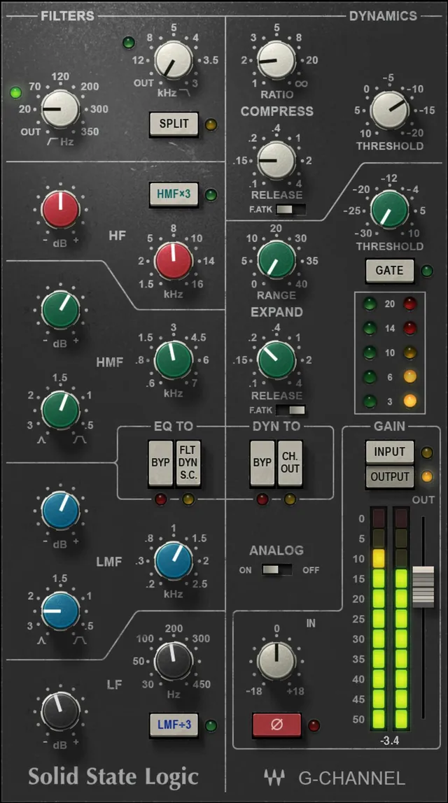
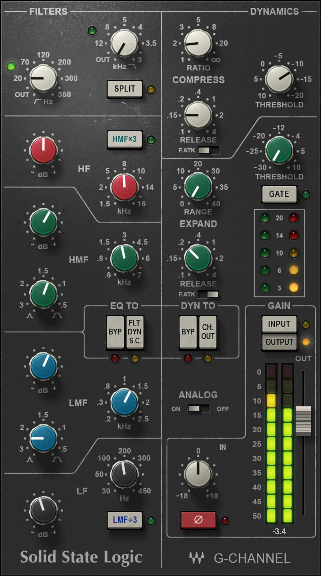
Waves SSL G-Channel is a channel-strip plugin modeled after the SSL SL4000 G Series, combining the console’s channel dynamics with the 383 G EQ. The dynamics section includes compression/limiting and expansion/gating; the EQ is a four-band design with high- and low-pass filters, variable-Q mids, fixed high/low shelves and frequency multipliers on the mid bands. The G-specific FLT Dyn S-C description routes filters to the dynamics sidechain; whether it includes the mid and shelf EQ bands remains unresolved. [1][2]
The current Waves manual covers SSL E-Channel and G-Channel together because the dynamics architecture is shared. The EQ sections differ materially, so this article uses the G-Channel-specific control section rather than copying E-Channel bell/shelf behavior into the G model. [1]
My Short Version
Use Threshold, Ratio, Attack and Release for compression; the plugin applies automatic compressor makeup gain derived from Ratio and Threshold. Use the green Expander/Gate section when you need downward expansion or gating, and use Gate to switch from the default expander behavior to a gate. [1]
For EQ, start with the four G-Series bands. The HMF ×3 and LMF ÷3 switches extend the mid-band frequency ranges, while Split moves the high- and low-pass filters ahead of the dynamics. If you want frequency-selective compression or gating, use FLT Dyn S-C to route the G-Channel filters to the dynamics sidechain. The manual's G-specific control text describes filter routing; its overview and product page describe EQ routing more broadly, so whether the G mid/shelf bands also enter the detector path remains unresolved. [1][2]
I did not audition or measure SSL G-Channel for this article. The explanations below are documentation-led.
What the G-Channel models
Waves documents SSL G-Channel as a model of the SL4000 G Series channel strip: the shared SL4000 dynamics section plus the 383 G EQ. The manual distinguishes this from SSL E-Channel, which uses the 242 “Black Knob” EQ. [1]
The manual also states a one-sample latency for the E- and G-Channel models in the documented version. That is a manual statement, not a new host measurement made for this article. [1]
Dynamics signal position
The dynamics section can operate pre-EQ by default or be moved post-EQ using the channel-output routing control. The manual’s shared overview says both E- and G-Channels support this pre/post relationship. [1]
The detailed Ch Out sentence happens to name E-Channel, but the same manual’s product overview explicitly describes the shared dynamics routing for both channel models. This article therefore treats post-EQ routing as documented shared behavior rather than extrapolating from the E-only EQ section. [1]
Compressor Ratio / Slope
The compressor Ratio/Slope control runs from 1:1 to infinity:1, with the upper extreme functioning as limiting. [1]
A lower ratio produces gentler gain reduction above threshold; raising it produces progressively stronger control. This is ordinary editorial interpretation of the documented ratio range, not a listening claim about how the analog model sounds at any setting.
Compressor Threshold
The compressor Threshold range is +10 dB to -20 dB. [1]
Lowering Threshold makes more of the input exceed the compressor’s operating point. The manual also states that compressor makeup gain is calculated automatically from the Ratio and Threshold settings to help maintain output level. [1]
Because the plugin models console behavior, do not assume the automatic gain compensation guarantees identical peak level or loudness before and after processing; this article did not perform that measurement.
Compressor Attack
The compressor Attack is a two-state fast/slow behavior rather than a continuously ranged time control. [1]
- F.ATK off / Slow — auto-sensing and program dependent.
- F.ATK on / Fast — 1 ms. [1]
The program-dependent mode is the documented default behavior in the overview. Use Fast when the goal is to engage the compressor more quickly; use Slow when you want the console’s program-sensitive attack behavior. The second sentence is workflow guidance, not an audition result.
Compressor Release
Compressor Release is continuously adjustable from 0.1 to 4 seconds. [1]
Shorter values recover gain reduction faster; longer values hold the gain change longer. Choose it in relation to the source’s envelope instead of treating one time as universal.
Compressor gain-reduction indicator
The shared dynamics section has a dedicated activity/level indicator for the compressor/limiter. The manual separately documents an expander/gate indicator, so the two processes can be watched independently even though they share gain-change circuitry. [1]
This article does not convert that display into a new measured transfer curve or claim an undocumented meter calibration.
Expander/Gate Threshold
The green Expander/Gate Threshold range is -30 dB to +10 dB. [1]
The threshold sets where the downward dynamics section reacts. In Expander mode the attenuation changes more gradually; switching to Gate changes the operating mode to gating. [1]
Expander/Gate Range
Range controls the maximum attenuation available from the expander/gate and runs from 0 to 40 dB. [1]
At 0 dB there is no available attenuation from this section. Larger settings permit deeper reduction when the detector closes the expander/gate.
Expander/Gate Attack
The Expander/Gate Attack follows the same two-state pattern as the compressor. [1]
- F.ATK off / Slow — auto-sensing and program dependent.
- F.ATK on / Fast — 1 ms. [1]
This affects how quickly the downward dynamics section opens/responds when the detector state changes.
Expander/Gate Release
Expander/Gate Release is adjustable from 0.1 to 4 seconds. [1]
Shorter release closes/reduces more quickly; longer release produces a slower return. The appropriate value depends on the decay of the material and how audible you want the gating/expansion envelope to be.
Gate switch
The Gate switch changes the green section from its default Expander mode into Gate mode. [1]
That distinction matters because Range and timing controls remain part of the same section, but the detector/gain-change behavior is not the same task as gentle expansion.
Dyn To / dynamics bypass
The dynamics routing section includes Bypass and the post-EQ channel-output routing option. [1]
Waves cautions that dynamics Bypass does not produce a mathematically flat digital path; it models the response of the SSL channel strip in its flat state. That is a useful limitation when null-testing or expecting a bit-transparent bypass inside the modeled strip. [1]
High-pass and low-pass filters
The G-Channel has both low-pass and high-pass filters. [1]
- Low Pass: 3 kHz to 22 kHz, 12 dB/octave, specified at the -3 dB point.
- High Pass: 16 Hz to 350 Hz, 18 dB/octave, specified at the -3 dB point.
- Turning either filter fully left bypasses that filter. [1]
Use the high-pass filter for low-frequency cleanup and the low-pass for upper-band restriction; those are ordinary applications of the documented filters, not a claim about a particular source.
Split
Split places the low-pass and high-pass filters before the dynamics processors in the signal chain. Without Split, the filters follow the same routing as the EQ section. [1]
Split changes the filters' position in the audio path. The G-specific FLT Dyn S-C text instead describes feeding filters to the dynamics detector; the broader overview does not establish whether all G EQ bands are included. [1]
High-frequency EQ
The magenta high-frequency band is a fixed shelving band. [1]
- Frequency: 1.5 kHz to 16 kHz.
- Gain: ±17 dB shelving. [1]
Unlike E-Channel, the G-Channel high and low bands remain shelves; there is no G-Channel Bell switch documented for these bands. [1]
High-mid EQ
The green HMF band is a parametric mid band. [1]
- Frequency: 600 Hz to 7 kHz before the multiplier.
- Q: 0.1 to 3.5.
- Gain: approximately ±20 dB at Q 3.5 to ±15 dB at Q 0.1.
- HMF ×3 multiplies the selected frequency by three. [1]
The multiplier extends the useful high-mid reach without changing the fact that this is the same HMF band.
Low-mid EQ
The blue LMF band is the second parametric mid band. [1]
- Frequency: 200 Hz to 2.5 kHz before the divider.
- Q: 0.1 to 3.5.
- Gain: approximately ±20 dB at Q 3.5 to ±15 dB at Q 0.1.
- LMF ÷3 divides the selected frequency by three. [1]
The divide switch extends the band downward for lower-frequency shaping.
Low-frequency EQ
The black low-frequency band is a fixed shelf. [1]
- Frequency: 30 Hz to 450 Hz.
- Gain: ±17 dB shelving. [1]
Again, do not import E-Channel’s LF Bell behavior into G-Channel; the shared manual explicitly distinguishes the two designs. [1]
EQ bypass and FLT Dyn S-C
The G-Channel EQ routing area provides an EQ Bypass state and the FLT Dyn S-C sidechain-routing function. In the G-specific control description, FLT Dyn S-C switches the filters into the dynamics sidechain. The manual overview describes the equalizer more broadly as routable to the sidechain; the exact scope of the G control is therefore documented inconsistently. [1]
As with dynamics bypass, Waves notes that EQ Bypass models the channel strip’s flat hardware response rather than promising a perfectly flat digital pass-through. The G-specific control description says FLT Dyn S-C switches the filters into the dynamics sidechain, allowing frequency-selective detection. The shared overview says the equalizer can route to the sidechain; the manual does not clarify whether the G control includes its mid and shelf bands. [1]
That makes de-essing or frequency-sensitive gating possible without claiming that G-Channel is a dedicated dynamic-EQ processor.
Input Trim
The master section includes Input Trim with a documented ±18 dB range. The manual gives an alignment reference of -18 dBFS = 0 dBu. [1]
Input Trim is the sensible place to manage how hard the modeled strip is driven before judging compression, EQ or analog coloration. That is workflow guidance; no saturation threshold was measured here.
Output fader
The Output fader sets final channel output level. [1]
Use it after EQ/dynamics changes to manage the level leaving the plugin rather than treating automatic compressor makeup gain as the only level control.
Input/Output metering
The master meter can be switched between Input and Output monitoring using the controls above the meter. The level indicator is documented in dBFS, even though several channel parameters are described in dB/dBu-style console terms. [1]
That unit distinction is worth keeping explicit when comparing the on-screen meter with threshold or calibration values.
Analog
Analog enables or disables the modeled analog behavior. Waves documents that turning Analog off disables the analog emulation. [1]
This article does not claim a specific noise level, harmonic spectrum or CPU difference for Analog on/off because no current native measurement was performed.
Phase / polarity
The Ø control reverses input polarity. [1]
Use it as a polarity tool, not as a substitute for timing alignment or stereo phase analysis.
WaveSystem toolbar
The current Waves shared toolbar provides preset loading/saving, comparison, undo/redo and interface resizing. [1]
Those are shared WaveSystem functions rather than SSL processing parameters, so they are accounted for here without presenting them as part of the modeled console signal path.
A practical G-Channel workflow
Start with Input Trim and confirm that you are not feeding the strip at an unintended level. If cleanup is needed, set the high- and low-pass filters first; use Split only if you specifically want those filters ahead of the dynamics. [1]
Shape broad tone with the fixed HF/LF shelves and use HMF/LMF for more focused work. The ×3 and ÷3 switches are useful when the nominal mid-band range does not reach the area you need. [1]
Then set compressor Threshold and Ratio, choose program-sensitive or 1 ms attack, and set Release. If expansion/gating is useful, set its Threshold, Range, timing and Expander/Gate mode independently. For frequency-selective detection, use FLT Dyn S-C. Finish with the output fader and meter the output. [1]
This is a conservative documentation-based sequence; I did not listen to these settings.
Best for / skip if
SSL G-Channel is best for someone who wants console-style EQ, compression and expansion/gating in one strip, especially when the G-Series shelf/mid architecture and detector-routing options are useful. [1][2]
Skip it if you specifically need E-Channel’s switchable HF/LF bell behavior, a modern dynamic-EQ display, or a processor whose bypass is intended to be bit-transparent. The first distinction is documented in the shared manual; the latter two are scope distinctions, not quality judgments. [1]
Limitations and evidence boundary
This article is documentation-led. I did not audition SSL G-Channel, measure harmonics/noise, verify one-sample latency in a current host, measure attack/release curves, or compare SSL G-Channel sonically with SSL E-Channel, EV2 or hardware.
The current product-linked SSL manual's complete G-Channel control sections were reviewed. The shared manual documents pre/post-EQ dynamics routing for both channel models in its overview, while the detailed Ch Out sentence names E-Channel only; the article preserves this attribution caveat. The manual overview also describes EQ routing to the dynamics sidechain broadly, while the G-specific FLT Dyn S-C control text says it switches filters into the sidechain. Whether the G switch routes all EQ bands remains unresolved; this is not a claim about installed-plugin behavior. [1]
Related guides
Useful official relationships are SSL E-Channel for the 242 E-Series EQ variation, SSL EV2 Channel for Waves’ newer SSL channel model, and SSL G-Master Buss Compressor for the separate stereo-bus dynamics processor.
Bottom line
SSL G-Channel is a full console-style channel strip, not just an EQ. Its shared SL4000 dynamics section provides compression/limiting and expansion/gating, while the 383 G EQ adds fixed shelves, variable-Q mids, range multipliers, filters and detector-routing options. The routing controls allow filters to move before the dynamics. The G-specific FLT Dyn S-C description feeds filters to the dynamics sidechain; broader manual/product EQ wording does not resolve whether the G mid and shelf bands also enter that detector path. [1][2]
Sources
Checked October 17, 2026. No listening or native-host test was performed.
- Waves SSL E-Channel & G-Channel User Manual, current product-linked manual; complete G-Channel controls parsed and G-specific EQ page visually inspected.
- Waves SSL G-Channel product page, current product identity and positioning.
- Waves Graphic Library, current SSL G-Channel listing and image-reuse rule requiring a relevant Waves product backlink.
FAQ
What is Waves SSL G-Channel modeled on?
Waves says SSL G-Channel models the SL4000 G Series channel strip, combining the shared channel-dynamics section with the 383 G EQ. The EQ and dynamics appear side by side in the software interface. [1]
How is SSL G-Channel different from SSL E-Channel?
The manual describes shared dynamics architecture, but different EQs: G-Channel uses the 383 G EQ with fixed HF/LF shelves and HMF×3 / LMF÷3 range switches; E-Channel uses the 242 EQ and has Bell controls for its HF/LF bands. [1]
How fast is the SSL G-Channel compressor attack?
With F.ATK off, the manual describes the attack as auto-sensing and program dependent. With F.ATK on, it specifies 1 ms. The overview identifies program-sensitive attack as the default. [1]
What does the Gate switch change?
The green section operates as an expander by default. The Gate switch changes it from Expander mode into Gate mode; the manual lists a -30 to +10 dB threshold and 0 to 40 dB range for the section. [1]
What does Split do on SSL G-Channel?
Split places the high-pass and low-pass filters before the dynamics processors. Without Split, the filters follow the routing of the EQ section. [1]
What does FLT Dyn S-C do on G-Channel?
The G-specific control description says FLT Dyn S-C switches the filters into the dynamics sidechain. The manual overview and product page describe EQ-to-sidechain routing more broadly, so whether the G switch also routes the mid and shelf EQ bands is not resolved by those descriptions. [1][2]
What does Input Trim do, and how is its meter calibrated?
Input Trim adjusts the channel input by ±18 dB. The manual gives -18 dBFS = 0 dBu as its alignment reference; the master level indicator itself reads in dBFS and can switch between input and output. [1]
What does turning Analog off mean?
The manual says switching Analogue off disables the analog emulation. It does not provide a measured noise, harmonic or CPU comparison, and this review did not test those outcomes. [1]

About the Author
Joseph Nilo has been working professionally in all aspects of audio and video production for over twenty years. His day-to-day work finds him working as a video editor, 2D and 3D motion graphics designer, voiceover artist and audio engineer, and colorist for corporate projects and feature films.